SoC Integration
This section describes the functional details of NANHU top-level interfaces. It's worth noting these are the typical configurations and the user may specify different architecture parameters.
Clock and Reset
NANHU has two clock domains:
-
One clock domain for the cpu core (
io_clock). All clock in CPU core isio_clock. -
One clock domain for jtag (
io_systemjtag_jtag_TCK).
NANHU has the following reset signals. All Reset signals are Asynchronous Resets.
-
io_resetis internally synced with the clockio_clock. Active high. -
io_systemjtag_resetis internally synced with the clockio_systemjtag_jtag_TCK. Active high.
There are two types of synchronizers in the RTL. All instances are used to synchronize the reset.
-
AsyncResetSynchronizerPrimitiveShiftReg(synchronize reset fromjtag_clocktoio_clock, from low frequency to high frequency) -
ResetGen/ResetGenDFT(used to synchronize for bothjtag_clockandio_clock, depending on the instantiations)
AXI Interface
For our definitions of the three ports,
- 256-bit AXI Memory Port: for CPU to access DDR (CPU is the master)
Address space: DDR space (0x8000_0000 to 0xf_ffff_ffff)
AXI ID width: 6-bit
Number of outstanding transactions: 56 (max. supported by L3 cache)
Max transaction size: 64 bytes
Number of IDs: 64
Max number of outstanding transactions per ID: 1
- 64-bit AXI Peripheral Port: for CPU to access peripherals (CPU is the master)
Address space: peripheral slaves space (0x0000_0000 to 0x7fff_ffff)
AXI ID width: 2-bit
Number of outstanding: 1 for instruction and 1 for data for each core
Max transaction size: 8 bytes
Number of IDs: 4 (though the ID is 4-bit, most of them are not used)
Max number of outstanding transactions per ID: 1
- 256-bit AXI DMA Port: for peripherals to access CPU/DDR (CPU is the slave)
Address space: DDR space (0x8000_0000 to 0xf_ffff_ffff)
AXI ID width: 8-bit
Number of outstanding supported by CPU: 32
Different transaction sizes and transactions per ID are supported. They are changed into 256-bit TileLink transactions internally. One AXI transaction may be split into multiple TileLink transactions.
This DMA port allows the peripherals to access DDR under coherency with the CPU caches. They can send standard AXI aw/w/ar requests to this port to write/read the DDR. Memory coherency is supported in the DMA port by the L3 cache. No explicit action is needed to sync the data with CPU.
Note: RISC-V defines a weak memory order. Load and store instructions are not required to be visible to other harts (CPU cores, DMA devices, etc) before an explicit memory barrier instruction like fence. For example, in NANHU, data in store queue and committed store buffer is not under coherency with the
CPU caches. To read newly stored data through DMA AXI port, a fence instruction must be used in software to make the CPU stores visible to the coherent cache hierarchy. This is a RISC-V requirement, not a bug/issue of NANHU.
Memory Map
There are three main regions:
-
Peripheral slaves space 0x0000_0000 to 0x7fff_ffff
-
DDR space: 0x8000_0000 to 0xf_ffff_ffff
-
DMA to access DDR: 0x8000_0000 to 0xf_ffff_ffff
Peripherals in the Peripheral address space is mostly determined by the SoC.
Default PMA is configured according to NANHU mamory map. Illegal memory access will cause access fault exceptions. Please remember to update the default PMA settings if you need to change the peripheral address mappings.
Internal peripheral address space:
| Device | Start Address | End Address |
|---|---|---|
| CLINT | 0x3800_0000 | 0x3800_ffff |
| BEU | 0x3801_0000 | 0x3801_ffff |
| Debug Module | 0x3802_0000 | 0x3802_0fff |
| L3CacheCtrl | 0x3900_0000 | 0x3900_0fff |
| PLIC | 0x3c00_0000 | 0x3fff_ffff |
Real-Time Clock (CLINT)
By default, the real-time clock in NANHU operates at 1/100 frequency of the CPU clock io_clock.
It can be optionally configured with an external real-time clock input io_rtc_clock. This clock usually operates at a fixed frequency ranging between 1MHz ~ 100MHz. The frequency is implementation defined and used by software in device tree. Example is shown in the southlake branch.
Interrupt
There are local (CLINT) and global (PLIC) interrupt controllers available with NANHU core. The PLIC and CLINT as shown in the below figure are for dual-core configuration.
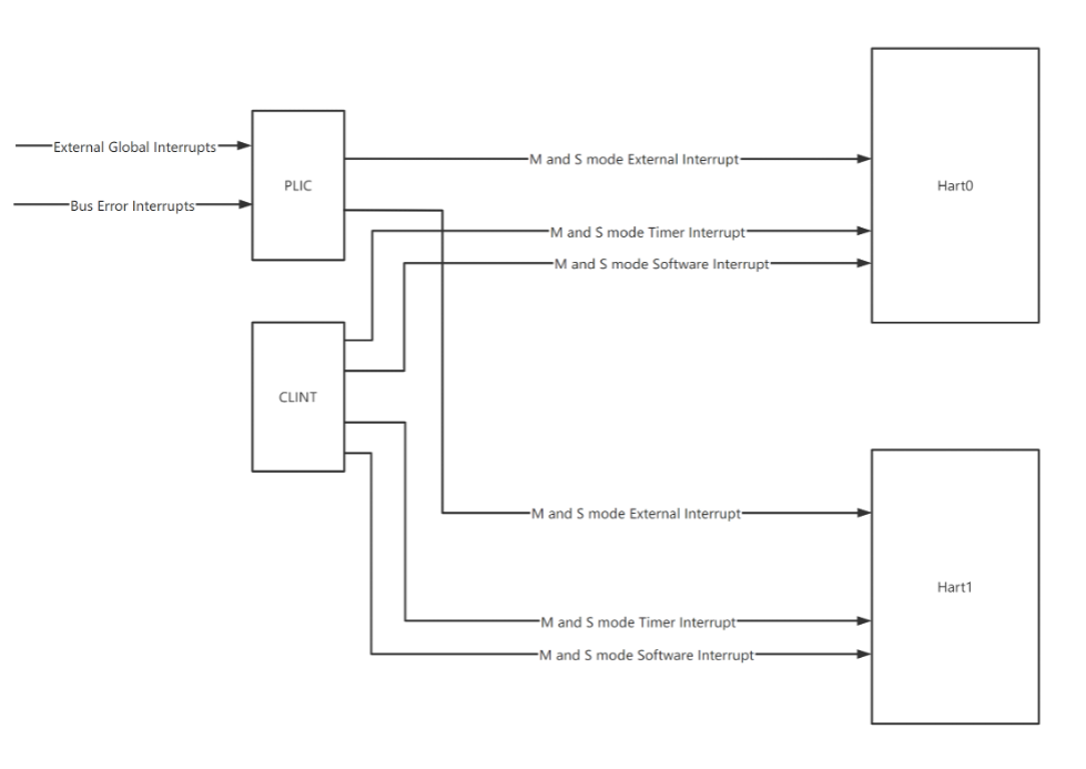
Local interrupt sources in NANHU includes timer interrupt and software interrupt. All the local interrupts are generated by CLINT for S-mode and M-mode.
Global interrupt controller follows the RISC-V Platform-Level Interrupt Controller Specification. PLIC is connected via 64-bit TileLink.
Below is the interrupt number mapping in PLIC. Interrupt 0 is always reserved by the PLIC.
| Interrupt No. | name | description |
|---|---|---|
| 0 | Reserved | - |
| 1~64 | external interrupt | From top-level io_extIntrs |
| 65 | bus error interrupt 0 | Core 0 bus error interrupt |
| 66 | bus error interrupt 1 | Core 1 bus error interrupt |
The global interrupt sources in NANHU includes external global interrupts and bus error interrupts. External global interrupts are generated by external devices. The bus error interrupts are generated by CPU hart0 and hart1.
Debug
NANHU implements RISC-V External Debug Support Version 0.13.2.
Wait for Interrupt (WFI)
By default, NANHU implements WFI as NOP.
It can be optionally configured to behave as the real wait-for-interrupt. Example is shown in the southlake branch.
However, it's worth noting the software must handle the case WFI is treated as NOP or WFI returns without a taken interrupt, even if NANHU is configured with the real wait-for-interrupt mode.
You can refer to the RISC-V privledge manual for more information in Section 3.3.3 (Wait for Interrupt). We cite some requirements below.
If the event that causes the hart to resume execution does not cause an interrupt to be taken, execution will resume at pc + 4, and software must determine what action to take, including looping back to repeat the WFI if there was no actionable event.
As implementations are free to implement WFI as a NOP, software must explicitly check for any relevant pending but disabled interrupts in the code following an WFI, and should loop back to the WFI if no suitable interrupt was detected.
Created: August 24, 2023